

The importance of troubleshooting electrical motors with infrared cameras
- Jan 4, 2019
- 3 min read
It’s no secret that infrared cameras, or thermal imagers, are handy for troubleshooting motor problems. They are also useful in monitoring motor condition for preventative maintenance in power generation, manufacturing and commercial plants. You can reveal motor operating condition by capturing thermal images of their apparent surface temperatures. In industrial environments, keeping accurate records of motor condition can help you avoid unanticipated malfunctions in critical systems.
Simply put, if these systems fail, companies see rises in cost due to increases in demand of labor and material. If unaddressed, businesses risk harming their profitability and the health of their employees and customers.
The onset of motor failures can often be detected by a variety of techniques, including vibration, ultrasound and thermal imaging. Creating regular inspection routes that include thermal images of all critical motor/drive combinations and tracking to those baseline images will help you determine whether a hotspot is unusual or not, and help you verify if the repairs were successful.
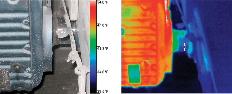
Properly functioning bearings should show cool temperatures
What to look for?
All motors should list the normal operating temperature on the nameplate. The exterior surface temperature, detected by the infrared camera, is an indicator of the internal temperature. As the motor gets hotter inside, it also gets hotter outside. An experienced thermographer who is also knowledgeable about motors can use thermal imaging to identify conditions such as inadequate airflow, impending bearing failure, shaft coupling problems, and insulation degradation in the rotor or stator in a motor.
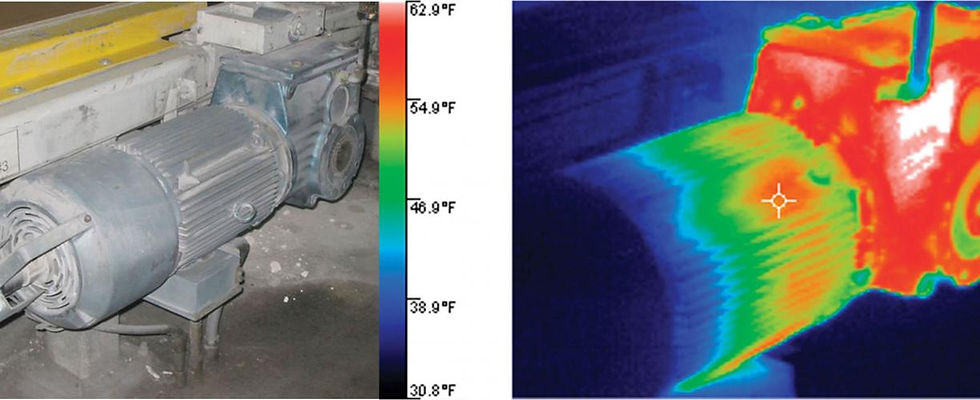
This thermal image shows a cool motor on the left and a hot gearbox on the right, with an especially white-hot anomaly.
What represents a “red alert”?
The highest repair priority should go to equipment conditions that pose a safety risk. Each motor has a maximum operating temperature that usually appears on its nameplate and represents the maximum acceptable rise in temperature of the motor, above ambient. (By design, most motors cannot function in ambient temperatures that exceed 40 °C.) Each 10 °C rise above its rated temperature typically cuts a motor’s life in half.
What’s the potential cost of failure?
While you might be a third-party contractor, it’s important to know what’s at stake. For a specific motor, could do an analysis based on the cost of the motor, the average amount of time a line is down from a motor failure, the labor required to change out a motor, etc. Of course, productivity losses from downtime vary from industry to industry. For example, lost production from a papermaking machine can be as much as $3,000 per hour while in the steel casting industry losses can be as high as $1,000 per minute. These obvious financial incentives to stay ahead of motor component degradation make thermal imaging inspections even more compelling.
Follow-up actions for overheating motor symptoms
Inadequate airflow. If a brief shutdown is possible without affecting the plant process, shut off the motor long enough to perform minor cleaning on the air intake grills. Schedule a thorough motor cleaning during the next planned plant shutdown.
Unbalanced voltage or an overload. The usual cause, a high-resistance connection in the switchgear, disconnect, or motor connection box, can usually be pinpointed by a thermographic inspection and This thermal image shows a cool motor on the left and a hot gearbox on the right, with an especially white-hot anomaly. confirmed using a multimeter, clamp meter or a power quality analyzer.
Impending bearing failure. When the thermal images indicate an overheating bearing, generate a maintenance order to either replace the bearing or lubricate the bearing. While somewhat expensive and requiring an expert, vibration analysis can often help you determine the best course of action.
Insulation failure. If it will not too greatly impact production, de-rate the motor in accordance with NEMA standards. Generate a work order to replace the motor as soon as possible.
Shaft misalignment. In most cases, vibration analysis will confirm a misaligned coupling. If a shutdown is possible, dial indicators of laser-alignment devices can be used and the misalignment can be corrected then and there.
Whenever you discover a problem using a thermal imager, use the camera’s software to document your findings in a report that includes a thermal image and a digital image of the equipment. It’s the very best way to communicate any problems you discover, as well as their suggested repairs.
Original post: click HERE


Comments